 .
.This project acts as a replacement of Part 3 of the offline book (www.LearnOpenGL.com). In it we see the use of meshes. The site uses the library Assimp for loading models. We will use another library, Gltf. We will write a number of programs. We start with two subclasses of Geometry, the Cube and the Sphere class. After this we will write a simple loader for a Gltf file and load with it the same model as is used in Chapter 21 of the book (the original nanosuit used by Crytek’s game Crysis). The programs that use the class Geometry (cubes_spheres.ts etc.) are put in the folder /ts/Ch21/.
In our project we will create the subdirectory geometry. This directory is at the same level as the common subdirectory and will contain classes like Cube and Sphere and also the Gltf loader.
The classes Cube and Sphere (and other similar classes) are subclasses of VertexObjects.
A VertexObject contains the vertices and indices of a geometry. In WebGL a vertexobjext is used to create a WebGLVertexArrayObject. The vertices are in a buffer that has all the properties of the object-points in space (its coordinates, normal, colors, etc.). The indices define the triangles (we no longer draw object without indices). A VertexObject is a subclass of AccessorObject. So, a vertexobjext has attributes + accessors that describe the layout of the content of the vertices buffer, similar to the way it is done in a WebGLVertexArrayObject. So, we can ask a vertexObject how many attributes it has, in what position an attribute is found and what type it has.
Others call a VertexObject object a geometry. We use the name VertexObject, because that is what it is, the data needed to create a WebGLVertexArrayObject. The predefined subclasses are objects like a cube, a sphere and a tetraheader, so something can be said in favor of the name of geometry. On the other hand, the use of texture coordinates in a VertexObject do not make us think of a geometry. We prefer the name VertexObject, but the name of its directory is geometry.
The accessors give access to the data in the vertices buffer and are stored in an array. In the attributes we map a selector to the number of the accessor. For instance in the Cube class we define the attributes as follows: attributes = {POSITION: 0, NORMAL: 1, TEXCOORD_0: 2}, meaning that for the attribute POSITION we use as accessor accessors[0], etc. We can define as many attributes as we like. The user of our classes are supposed to understand the meaning of the attributes. POSITION: 0 does not mean that we are using POSITION as the first element in the layout of the shaders!
The definition of VertexObject is as follows:
 /**
 * All subclasses must have indices defined.
 */
export class VertexObject {
    vertices: Float32Array;
    indices: Uint16Array;
    bytesStride: number;

    attributes: any = {};
    accessors: Accessor[] = [];

    constructor(bytesStride: number) {
        this.bytesStride = bytesStride;
    }mater
}This program is another version of program lighting_maps_specular.ts of chapter 15. This time with a cube and a sphere that get imported from VertexObject.ts, so the program starts with the include of the class definitions using: import { Sphere2, Cube } from '../../js/geometry/VertexObjects.js';
If we look at the definition of the class Sphere2 we see that it is similar to the one found in the LearnOpenGL.com site. In this program we use this Sphere2 class. To render a sphere2 we must use the gl.drawelements with gl.TRIANGLE_STRIP option. In later programs we use the class Sphere that will be rendered with the usual gl.TRIANGLES option.
To create a VertexArrayObject for a sphere the code starts with creating a sphere:
sphere = new Sphere2(12, 12);
This is a sphere with 12 horizontal slices that has also 12 subdivisions through north and sout pole. The number of vertices is much larger than of a cube and still the subdivisions are still visible.
To create the VertexArrayObject for the sphere we have made code that can be used for a cube as well. The code can be found at the end of our file, it is the function function createVAO(vo: VertexObject, layout: any). When calling this function the layout of the attributes in the shader must be given. It returns a WebGLVertexArrayObject.
Drawing the object is done using drawElements (always using indices): gl.bindVertexArray(myVAO); gl.drawElements(gl.TRIANGLES, myObject.indices.length, gl.UNSIGNED_SHORT, 0);
but as already mentioned, when using Sphere2 with TRIANGLES replaced by TRIANGLE_STRIP.
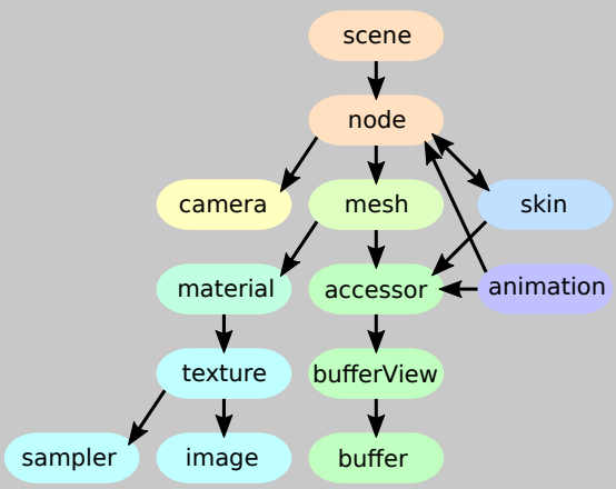
In the code of LearnOpenGL the library Assimp is used to import models/meshes. We will use another similar tool, glft. An overview is given in this short reference, that has the following image in it: .
As we see there, the glft files not only have meshes but contain also the materials, animations, skinning and morphing. Also the releation between the meshes is given in a scene graph. For now we only will load the meshes. A gltf mesh contains a list of gltf primitives. And a gltf primitive is more or less a VertexObjects object.
Note that in the book another concept of mesh is given In the book a mesh is more similar to a gltf primitive or a vertexObject (vertexObject meaning a VertexObjects object). It contains the data to fill a vao (vao meaning a GLVertexObjectArray object). The difference is that the books Mesh already contains the vao and other OpenGL buffers (as private fields) where a vertexObject only has the data, not the gl buffers. The book also has the concept of Model and that corresponds to a gltf mesh in the sense that a model contains a number of meshes. We will use the term mesh for an object that contains one or more vertexObjects.
A gltf primitive also has a material, a vertexObject not. We will use a default material and also a default shader, the ones used in Chapter 14. In Part 6 of the offline book of LearnOpenGL, that deals with physics based rendering (PBR), we will also load gltf materials, see in Part 6 the subdirectory ChGltf or a program that uses these materials.
A Gltf model has two parts, a description in json of the contents of the file and apart from that or in the same file a couple of buffers for the images and vertex data. When loading a gltf model we start with loading all the buffers needed. Usually all the vertex data are in one buffer and for the moment we are not yet interested in reading materials (textures / images). The loading is done in two stages. In the first stage the json and the buffers are read from file and the result is a GltfResource object with three fields: json, buffers and images with the obvious meaning. In the second phase we look in the json object and translate the content to the objects we use in our program.
The resource we will load is the cyborg that is in the resources of the book It is in the Wavefront .obj format, so the first thing to do is converting it to the .gltf format. This can be done by importing the .obj file in Blender, a famous free modelling program, and exporting it to the .gltf format. The exporter gives the following options: 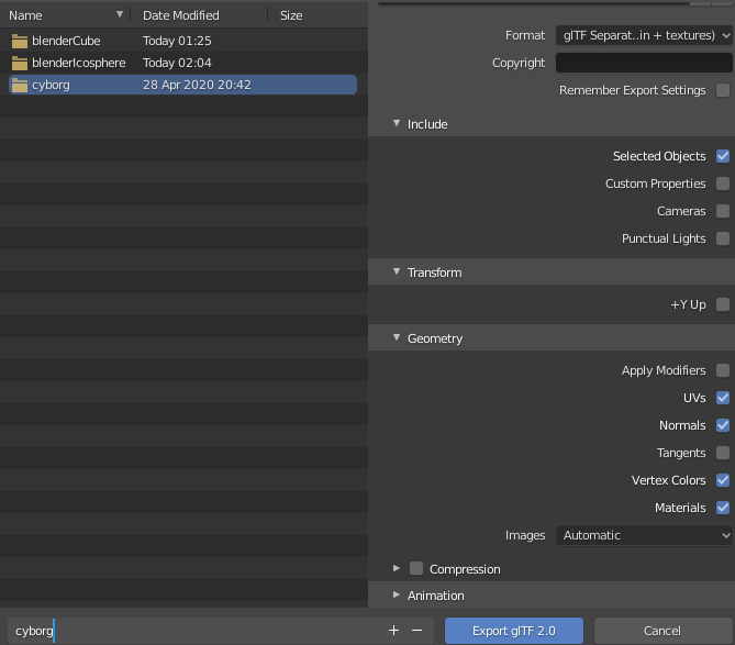 If the Format glTF+separate is chosen then the result will be in a file with .gltf extension, that has the json description, a .bin file that has the data for the meshes and one or more image files. We only use the .gltf and the .bin file.
We will be using javascript Promises. If the promise is resolved then the program continues with resourcesLoaded().The class GltfLoader has a method load() that tries to load the GltfResource from a url. In our program we use:
    // load our mesh
    let gltfUrl = "../../models/cyborg/cyborg.gltf";
    let gltfLoader = new GltfLoader();
    let promGltf = gltfLoader.load(gltfUrl);
    promGltf.then((res: GltfResource) => resourcesLoaded(res)).catch(error => alert(error.message));
Here resourcesLoaded is a callback function that takes a GltfResource as a parameter.
The code of resourcesLoaded is:
function resourcesLoaded(res: GltfResource): void {
    let model = new GltfModel(res);
    let meshes = model.getMeshes(false);
    if (meshes.length > 0)
        glMesh = createGlDrawable(model, meshes[0]);
    afterLoad();
}
With let model = new GltfModel(res) the resources res.json is read to find out about the bufferViews and accessors and the arrays GlftModel.bufferViews and Gltf.accessors are filled. All access to the data of a GltfModel is done using accessors that look at data in bufferViews. The bufferView data are copied from the buffers in the resource res. After this is done we can forget about the original buffers in res. Later on every bufferView will be copied to a corresponding gl-buffer.
After this is done the meshes can be read from the model with let meshes = model.getMeshes(false);. Again the json is inspected how many meshes there are and how many primitives each mesh has. For each primitive a VertexObject object is created. Actually the object is a subclass that also can have a material, but for now we forget about materials (the false in our call getMeshes indicates this).
Finally we create a drawable for the first mesh with glMesh = createGlDrawable(model, meshes[0]);. CreateGlDrawable is not part of the GltfModel.ts, but code in our own program 'load_gltf_mesh.ts'. In GltfModel.ts we have no references to OpenGL. In the createGlDrawable code the gl-buffers are created in the usual way (gl.createBuffer()) and then for the mesh in the model a vertex array object (vao).
The rendering itself is done using
    // render the gltf model
    for (let j = 0; j < glMesh.vaos.length; j++) {
        gl.bindVertexArray(glMesh.vaos[j]);
        gl.drawElements(gl.TRIANGLES, glMesh.vos[j].indexAccessor.countElements,
            gl.UNSIGNED_SHORT, glMesh.vos[j].indexAccessor.byteOffset);
    }
After this we see our cyborg appearing: 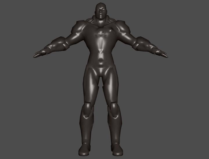
In the previous program we loaded a mesh from a gltf file with only one mesh in it, the cyborg. If we have more than one mesh in the file we would like to position them relative to each other and that is one of the reasons a gltf file has a nodes structure called a scene. There can be more than one scene in a file, but that is uncommon.
A Gltf scene has a collection of nodes, each of them is the start node of a tree of other nodes. Every node can have a matrix that tells how the node is positioned relative to its parent. This information can also be given in TRS notation (using a field for Translation, Rotation and Scale).
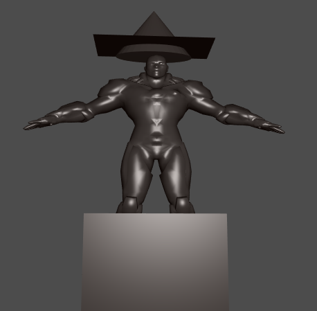
For a demonstration we now have a new model made in Blender where next to our cyborg we have a cube, a cone and a plane.The cone and the plane are combined to form some kind of awkward looking hat (in blender we selected the cone and the plane and used CTRL G to make one the parent of the other). And we exported the new model to 'cyborgObjCam.gltf'. If we look in the json structure of the .gltf file we now have as part of our nodes collection
        {
            "mesh" : 2,
            "name" : "Plane",
            "scale" : [
                1.502772331237793,
                2.303856611251831,
                1.7313028573989868
            ],
            "translation" : [
                -0.006150767672806978,
                -0.6517953872680664,
                0.275087833404541
            ]
        },
        {
            "children" : [
                4
            ],
            "mesh" : 3,
            "name" : "Cone",
            "scale" : [
                0.6654366850852966,
                0.43405479192733765,
                0.2514960765838623
            ],
            "translation" : [
                0.004092946648597717,
                4.179953575134277,
                -0.06918351352214813
            ]
        }
The plane is the fourth in the nodes collectio and the cone the fifth. We see that the plane is a child of the cone (by "children" : [4]). If we were to change the position of the cone the plane would automatically follow.
We also see that both nodes have a mesh attached to it (mesh 2 and 3 in the meshes collection). Not every node has a mesh attached to it.
The code in resourcesLoaded is now:
function resourcesLoaded(res: GltfResource): void {
    let model = new GltfModel(res);
    let scene: GltfScene = model.getScene(0);
    let cameras: GltfCamera[] = scene.getCameraNodes();
    if (cameras) { gltfCamera = cameras[0] };

    glScene = new GlScene(model, scene);

    afterLoad();
}
The gltf scene is found by calling getScene(0) on the model and after that we create a GlScene. We also get the first camera in the model. The code of the constructor of GlScene is:
class GlScene {
    drawMeshes: DrawMesh[];

    glBuffers: WebGLBuffer[];
    glMeshes: GlMesh[];

    constructor(model: GltfModel, scene: GltfScene) {
        // D3Q: for every bufferView there is one glBuffer
        this.glBuffers = new Array(model.bufferViews.length);
        // D3Q: for every mesh there is one glMesh
        this.glMeshes = new Array(model.meshes.length);

        let meshNodes: GltfNode[] = scene.getMeshNodes();
        this.drawMeshes = new Array(meshNodes.length);

        for (let i = 0, ilen = meshNodes.length; i < ilen; i++) {
            let mesh: GltfMesh = meshNodes[i].getMesh(false);
            let drawMesh = new DrawMesh();

            if (!this.glMeshes[mesh.id]) {
                this.glMeshes[mesh.id] = this.createGlMesh(model, mesh);
            }
            drawMesh.ppMatrix = meshNodes[i].ppMatrix;
            drawMesh.glMesh = this.glMeshes[mesh.id];
            this.drawMeshes[i] = drawMesh;
        }
    }

    private createGlMesh(model: GltfModel, mesh: GltfMesh): GlMesh {
        let glMesh = new GlMesh();
        ...
    }
}
In the GlScene we keep track of drawMeshes: DrawMesh[] (there are as many drawmeshes as there are references to one of the meshes in the scene), glBuffers: WebGLBuffer[] (there are as many glBuffers as there are BufferViews in the model) and glMeshes: GlMesh[] (there are as many glMeshes as there are meshes in the model).
First we find all the nodes in the scene that have a mesh attached to it. We then create a glMesh if it is not already done. We ask the node for its mesh and for its ppMatrix and the combination of both is a new drawMesh. It are the drawmeshes that are used in the render() method.
Every node has apart from the matrix that gives its spacial relation relative to its parent also a runtime ppMatrix in which this matrix is multiplied with the ppMatrix of its parent (ppMatrix = Parent Product matrix). This ppMatrix gives the spacial relation relative to the root of the scene.
In the render() we use the ppMatrices for our setting of the model matrix, where we also give the model an extra scaling:
    for (let i = 0, ilen = glScene.drawMeshes.length; i < ilen; i++) {
        // world transformation
        let model: mat4 = mat4.clone(glScene.drawMeshes[i].ppMatrix);
        let scale: mat4 = mat4.create();
        mat4.fromScaling(scale, vec3.fromValues(scaleModel, scaleModel, scaleModel));
        mat4.multiply(model, scale, model);
        setMat4vShader(lightingShader, "model", model);

        let m: DrawMesh = glScene.drawMeshes[i];
        for (let j = 0; j < m.glMesh.vaos.length; j++) {
            gl.bindVertexArray(m.glMesh.vaos[j]);
            gl.drawElements(gl.TRIANGLES, m.glMesh.vos[j].indexAccessor.countElements,
                gl.UNSIGNED_SHORT, m.glMesh.vos[j].indexAccessor.byteOffset);
        }
    }
And voila:
This model uses no scaling. We have to use a small value for scaling when using the 2CylinderEngine.gltf model (set scaleModel = 0.01), that is also in the models subdirectory.
Some final remarks